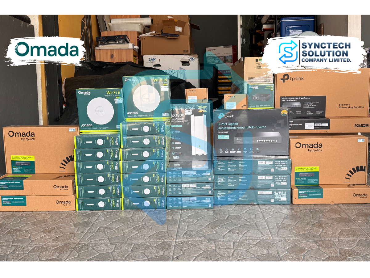
This project involved the design and deployment of a complete
network infrastructure for a newly constructed veterinary hospital.
Because the network was planned during the early stage of the building,
the gateway, switching, wireless network,
backbone connectivity, and network segmentation
could be designed as one integrated architecture.
The objective was not simply to provide Internet access
or install wireless access points.
The network was designed as part of the facility's digital infrastructure,
supporting multiple user groups, internal systems,
connected devices, and visitor connectivity.
TP-Link Omada SDN was selected as the central networking platform,
allowing the gateway, managed switches,
and wireless access points to be managed
within the same centralized environment.
Network Architecture Design
For a facility containing both indoor and outdoor service areas,
wireless design cannot be based solely on the number of access points.
The performance and manageability of the wireless network
also depend on switching, VLAN design,
uplink capacity, PoE infrastructure,
and the physical placement of network equipment.
The architecture was therefore structured around
the network gateway, managed PoE switching,
indoor wireless, outdoor wireless,
fiber optic backbone connectivity,
and centralized management.
Network segmentation was also considered from the beginning,
allowing different users and systems
to be logically separated through VLANs and SSIDs
rather than placing all devices on a single flat network.
Indoor Wi-Fi 6 Infrastructure
TP-Link EAP610 Wi-Fi 6 Access Points
were deployed throughout the planned indoor service areas.
The access points were positioned according to the intended usage zones
to provide structured wireless connectivity across the facility.
Wi-Fi 6 provides a modern wireless platform
suitable for environments containing a variety of connected devices,
while the Omada Controller allows wireless configuration
to be managed centrally.
SSIDs can be associated with different VLANs,
allowing wireless services for staff,
internal systems, and guests
to be logically separated within the same infrastructure.
Outdoor Wireless Coverage
TP-Link EAP610-Outdoor Access Points
were selected for outdoor service areas
where wireless connectivity was required beyond the main building.
Using dedicated indoor and outdoor access point models
allows each area to use equipment
that is better suited to its installation environment,
rather than relying on a single device type
throughout the entire project.
Wireless Roaming
Because users may move between different areas of the facility,
the wireless infrastructure was designed
to support roaming between access points.
This approach is particularly useful
in environments containing multiple access points,
where the wireless system is designed
as a coordinated infrastructure
rather than as a collection of independent hotspots.
Managed Switching & PoE Infrastructure
TP-Link SG2210MP Managed PoE+ Switches
form part of the switching layer
and provide both network connectivity
and Power over Ethernet for the wireless access points.
PoE simplifies access point deployment
by delivering network connectivity and power
through the Ethernet cabling,
reducing the need for separate power adapters
at each wireless installation point.
As managed switches,
the SG2210MP units can also support VLAN configuration,
port management, and structured network policies,
making the switching layer an active part
of the overall network architecture.
VLAN & Network Segmentation
A key design principle of the project
was to avoid placing every user and connected system
on the same network segment.
VLANs can be used to separate staff connectivity,
internal systems, guest Wi-Fi,
and other network services as required,
while SSIDs can be mapped
to the appropriate network segment.
This provides a more structured network environment
and makes future policy changes or expansion
easier to manage than a flat network architecture.
Gateway & Centralized Management
A TP-Link ER605 is used as the network gateway
and operates together with the TP-Link OC200 Hardware Controller
to provide centralized management of the Omada environment.
Administrators can view the status of the gateway,
managed switches, wireless access points,
and connected clients
through a single management interface.
Centralized management becomes increasingly valuable
as the number of network devices grows,
because configuration and device status
can be reviewed as part of one overall infrastructure
instead of managing each device individually.
Fiber Optic Backbone
Single-mode fiber optic connectivity
is used within selected parts of the network backbone,
together with TP-Link SM311LS SFP Modules.
Fiber connectivity provides greater flexibility
for network links over longer distances
without the same distance limitations
associated with conventional copper Ethernet.
Preparing fiber backbone connectivity
also provides a stronger foundation
for future network expansion
when additional network equipment
or service areas need to be added.
Why TP-Link Omada Was Selected
Omada was selected for this project
because it allows the gateway,
managed switches, and wireless access points
to operate within a common management platform.
This reduces management complexity
compared with operating multiple independent devices
that require separate configuration interfaces.
The same architecture can also accommodate
additional access points, switches,
and network segments in the future
without changing the overall management approach.
Lessons from the Real-World Deployment
One of the main lessons from this project
is that network planning for a new building
should begin during the infrastructure design stage,
rather than waiting until construction is complete
before deciding where network equipment should be installed.
Planning access point locations,
network racks, uplinks,
PoE switching, and fiber routes together
helps reduce installation limitations
and unnecessary changes later in the project.
Another important consideration
is that the number of access points alone
does not determine the quality of a wireless network.
Wireless performance and manageability
also depend on the switching infrastructure,
VLAN architecture, uplinks,
and management platform behind the access points.
Practical Design Guidance
For organizations building new facilities
or upgrading existing network infrastructure,
network design should begin by identifying
the different users, devices,
and systems that require connectivity.
VLANs, SSIDs, switching,
and wireless architecture
can then be designed around those requirements.
Indoor and outdoor areas should also be evaluated separately
according to their installation environments.
PoE capacity, uplinks, and backbone connectivity
should be planned for the actual deployment
while also allowing sufficient flexibility
for future network expansion.
Introducing centralized management from the beginning
can also reduce the operational burden
as the number of network devices increases.
Project Outcome
Following installation and configuration,
the network operates as an integrated architecture
covering the gateway, managed switching,
fiber backbone, and indoor and outdoor wireless infrastructure.
Network and wireless services
can be logically separated
according to their intended use,
while configuration and device status
can be monitored through the centralized Omada platform.
The infrastructure also provides a structured foundation
for future additions such as access points,
network segments, switches,
and other connected systems
without requiring a complete redesign.
Project Summary
This deployment demonstrates
how network infrastructure can be treated
as part of a building's core digital foundation
rather than simply as an Internet or Wi-Fi service.
By combining the gateway,
managed PoE switching,
fiber optic backbone,
indoor and outdoor Wi-Fi 6,
and centralized management,
the resulting architecture is structured,
manageable, and ready to support future requirements.